The final project for my Mechanical Systems Design course was to design and build a robot using custom parts and catalog components. The robot should climb as quickly as possible while holding a payload (see project description attached for more information on specific constraints). Since this project was done virtually due to COVID, the robot was designed and tested solely through CAD and simulation programs.
Design
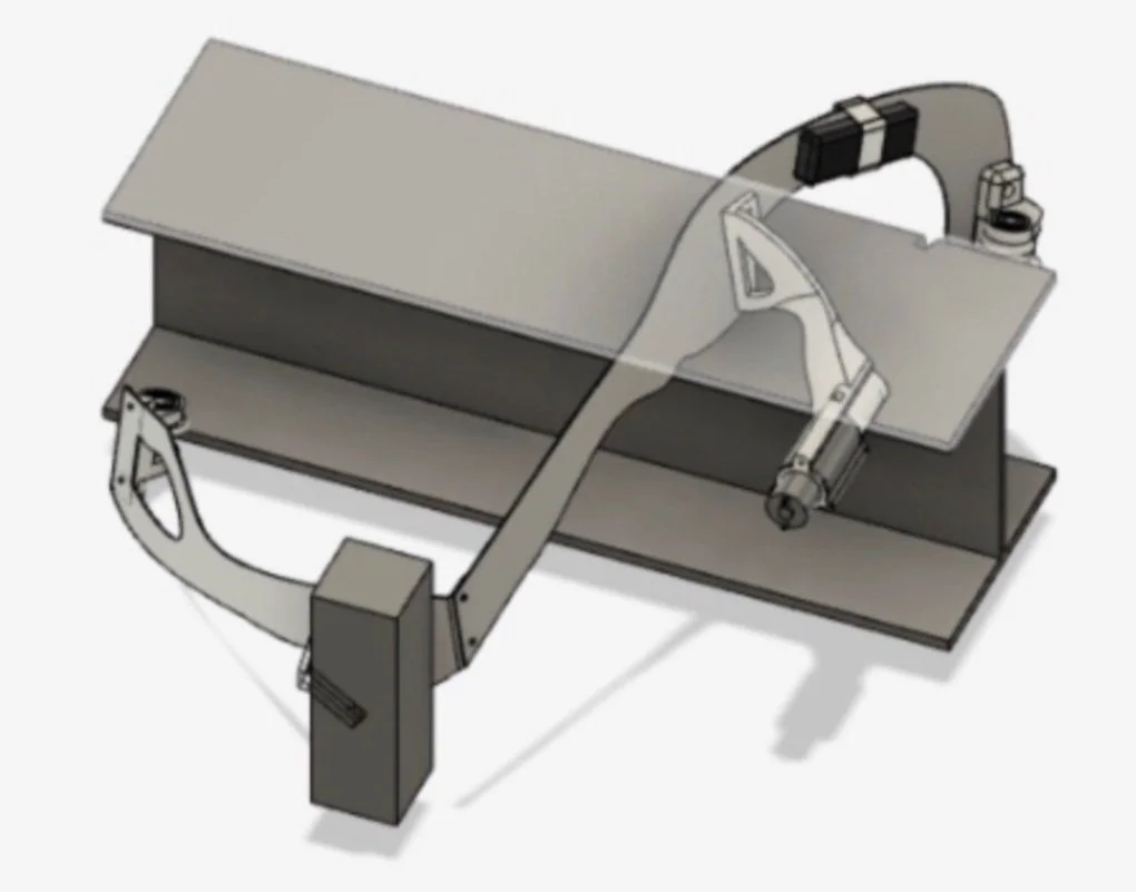
The frame of the robot was determined by identifying where powered and unpowered wheels would be placed. We created a three force member in the X-Y and X-Z plane by placing wheels with the assumption that a frame would connect them, and align the wheels axially in the Y-Z plane. We chose aluminum as it allowed for complex geometries and its material properties are extensively documented in CAD software.
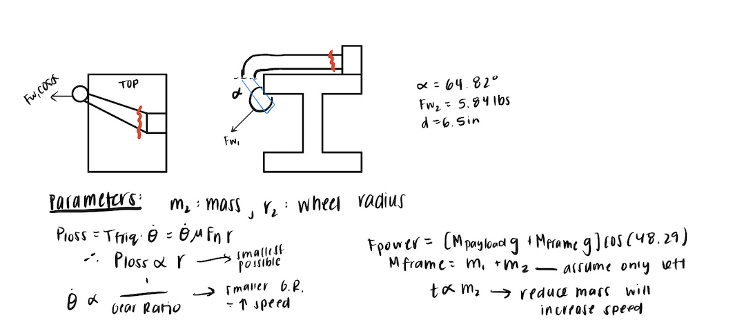
We started by choosing the maximum voltage in the motor operating range and then decided to operate our motor at the maximum output power from our our motor which would yield a faster climb time. For our gear train, we wanted to minimize the gear ratio we used so we could minimize the inefficiency and maximize transmission output power at the torque we needed and thus chose a small radius for the wheels to achieve this. ]
BOTEA
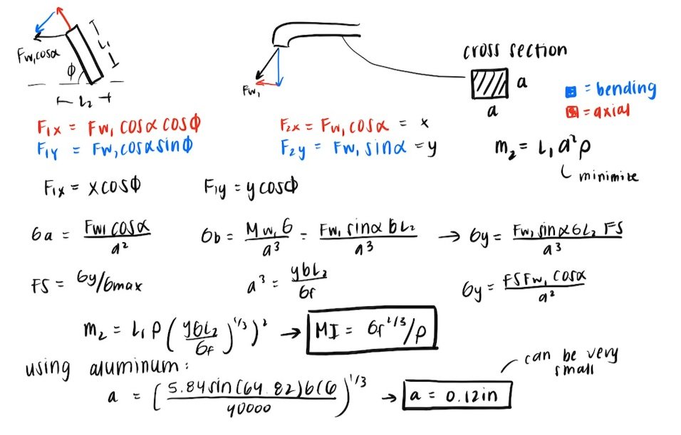
We completed a simplified analysis for the frame that holds the payload. This can be viewed below.
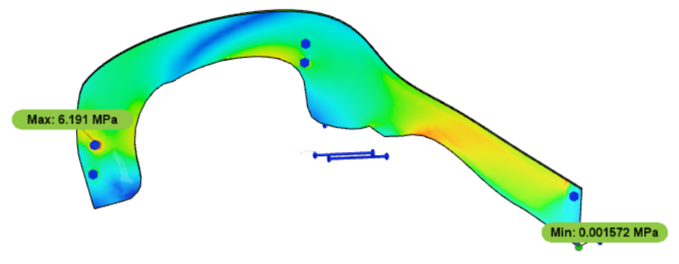
FEA
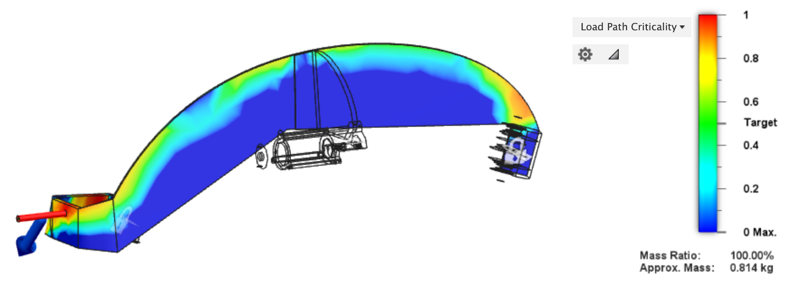
We also completed a detailed analysis for the frame with overlaid topology. This can also be viewed below.
Results
From these analysis, we were able to design an efficient and light-eight robot. The final assembly of our robot can be viewed below. You can also access the Final Project Report as well as our CAD files. Our robot successfully climbed to the top of the beam while carrying the payload. Additionally, our team won the prize for fastest climb time.